| <!--QiQu--> |

|
|
|
Home
Introduction Documentation QiQu Language QiQu Tutorials QiQu Samples State Machine Xml Mpe FW QiQuGen Developer's Corner Downloads Screenshots Contact Sponsoring |
State Machine ExampleAs MDA becomes more and more popular, the use of State Machines for modelling dynamic behaviour in software systems is no longer limited to industrial embedded real-time applications but is successfully applied to business applications as well. The mathematical consistent rules of a state machine allows to transform its graphical representation to a runtime environment automatically. At SBB (Swiss Federal Railway Company) state machines are used to define the behaviour of the next generation ticket vending machines. With QiQu the state machines modelled in Borland Together UML tool are automatically transformed to a Java implementation. For the implementation, a simple state machine framework based on the state pattern is used. The framework integrates smoothly into SBB's own Mono Channel Architecture (MCA). The following example uses a similar state pattern framework and shows how you can transform a UML state chart model to Java code using QiQu. It is an Eclipse project consisting of the model (Poseidon UML Model), transformation rules (QiQu scripts), state pattern framework (JAR library) and a simple application (Java class), everything you need to get a running system. To start with the example you first need Eclipse 3.1 with JDK 1.5 and QiQu Plugin installed. Please follow the instruction in the readme file. Download the zipped example here Representation of a State MachineThe State ChartThe State Chart provides a clear graphical representation of the state machine. It shows clearly the sequences and cycles of a class. 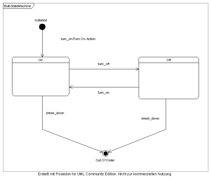 The State TableThe UML State Chart shows clearly which signal triggers a transition from one state to another. But it does not define all possible combinations of states and signals (each signal may potentially occur in each state). The tabular representation of the state machine shows the complete specification of the state machine. In the State Table, each column corresponds to a state, each row corresponds to a transition signal. The table below can be read as follows:
In real world applications some combinations of state/signal can not happen due, for example to physical constraints in a system. Those are marked as "can not happen". "undefined yet" In our example, the information which can not be visually modelled in the UML State Chart is defined as tagged values on the state model elements (see picture below). The state table is generated by a QiQu script using this information. 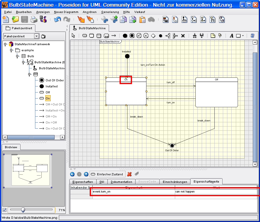 The UML model of the example was created with Poseidon 4.1 Community Edition (www.gentleware.com). |